Typically the impeller is a single propeller or turbine blade connected to a shaft that is driven by an electric motor at a fixed speed. Input fluid properties inlet conditions and main stage parameters.
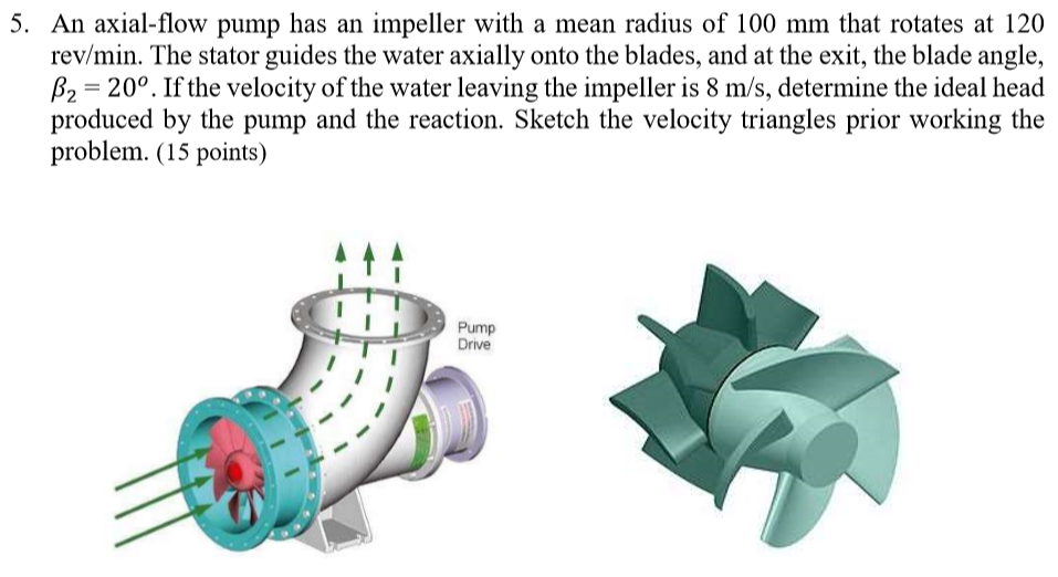
Solved 5 An Axial Flow Pump Has An Impeller With A Mean Chegg Com
Engineers coming from home and abroad factories widely employ one-dimensional flow theory to optimally design an impeller for a centrifugal pump 9 11.
. Impeller flow designs can take on three distinct types. The method can be used in CAD software to design axial-flow pumps. Determination of the main dimensions of the impeller 3.
An axial flow pump impeller all-operating-condition design method comprises the following steps that 1 parametric modeling of an axial flow pump impeller is performed namely 2k design parameters including. For design calculation the design parameters are taken as follows. Sizing design of Axial Flow Pump.
Thus the impeller forces the liquid into a rotary motion by impeller action. PropCads built in Library makes it easy to generate propeller and impeller geometries for axial flow pumps. Head H 10 m.
This link contains an excellent mixing impeller calculator as well as raw formulas for many of the parameters listed above. 𝐷ℎ 𝐷𝑑 𝐷𝑜 7 𝐷ℎ 0422 06 𝐷ℎ 025 𝑚 If the hub-ratio is 0422 the hub diameter is 025 m. Axial-flow and radial-flow and the mixing characteristics are shown in Figure 2.
Calculation of the impeller main dimensions of the impeller. The objective of this paper is to be design the impeller for a centrifugal caustic slurry pump to increase its power and efficiency and showing the advantage of designing parameters six blade turbine design changes from impeller comparing with the old material of a TURBINE. 5 The specific weight of the air in the impeller eye Fig 4.
6 Volume flow through impeller eye 7 Air horsepower 7hp overall 70 8 Brake horse power 9 Torque T Torque T 182608 lb-in Allowed shear stress 10 Shaft diameterd 15 in The shaft diameter D s is based upon the critical speed and deflection. For use as a design factor Equation I can be used to solve for the design velocity assuming a. Flow rate Q 1000 m3hour Head H 8 m Pump speed n 1400 rpm Gravitational acceleration g 981 ms2 Density of.
Quickly change number of blades blade areachor. Available only if the meridional direction is mainly radial. However one-dimensional flow theory which is based on Euler equations is convenient and simple.
End users began to experiment with impeller systems that combined axial and radial impellers. Hub must overlap shroud in z-direction about 50 or more. Axial-flow impellers generate currents.
Two alternative design modes. After selecting the suitable impeller outside diameter inner diameter or hub diameter of impeller can be determined by the following equation. Airfoil hydrofoil design or mean line design.
So the design data are required to design the centrifugal pump. Application of internal or user-defined approximation functions for defining impeller parameters. 2D axial Free-form 2D axial centrifugal mixed-flow impellers only.
Mixing constant laminar flow fluid dynamic viscosity. Guide vanes can be upstream or downstream from impeller. For design calculation the design parameters are taken as follows.
Therefore the impeller outside diameter for axial flow pump is taken as 06 m. The impeller of a typical axial flow pump and the flow through a radial flow pump are shown in the illustration below. The axial flow pump includes the impeller rotating inside a casing of sufficient length and that ensures uniform incoming and outgoing flow.
Hub must not have axial parts within blade area. Guide vanes are used to control airflow and fan static pressure. Finding the mean meridian flow hull and generating mean line blading.
Axial impellers only. Feasibility check of the input parameters. The axial flow pump impeller all-operating-condition design method adopts CFD numerical calculation the design accuray is high and optimization results are reliable.
Axial Flow Impeller Design Calculations. The following design strategy is implemented in the code. Axial flow impeller design calculations Nail artwork conjures up Absolutely everyoneIn case you are a colorful Woman Then you can certainly choose up brighter color tones for the nails if you want subtle items so definitely your temper will pick up on nail paints that happen to be a tad boring and less flashy.
Flow rate Q 200 m. Hub and tip diameter at inlet and outlet. By using controllers vane axial fans were widely used to control air flow.
Rotation speed revolutions per second laminar flow impeller diameter laminar flow power requirement. The method allows a mathematical description of the skeleton line as a parabola taking into account the entrance and exit angles of the blade. Up to 10 cash back details.
But this design was not successful due to a tendency of the gas to coalesce at the top of the vessel and because there was a general lack of knowledge. An investigation in to usage of new materials is required. There are two classes of impeller agitators.
POWER PUMPING NUMBERS OF VARIOUS IMPELLERS Axial Radial Flow Impellers Hydrofoil Impellers Impeller Style NP NQ Impeller Style NP NQ 4PBT45 162 086 4HP45 CONTACT FACTORY 4PBT32 10 071 3AL45 4RBT90 360 110 3AL39 4RSB90 252 095 3AM45 6RD90 475 123 3AH39 6RDC90 320 150 4AH45 Notes. Design Calculation of Impeller for Axial Flow Pump. International Journal of Scientific and Research Publications IJSRP 8 9 DOI.
So the design data are required to design the centrifugal pump. High noise levels and high initial cost of vane axial fans with variable vane guides make it uneconomical comparing to variable speed motors. Power requirement laminar flow Reynolds number 10.
At first the pitched-blade turbine Figure 2 was used as an upper impeller. Impeller is designed on the basic of design flow rate pump head and pump specific speed. Pump in the engineering field.
Propeller and turbine mixers. Circular 2D axial Straight 2D axial 2D radial Free-form 2D. This study relates to the impeller design of axial flow pump that can develop a head of 3 m and deliver 03 m3s of water at the speed of 1000 rpm.
Impellers can be designed to impart various flow characteristics to pump or tank media. An analytic method for designing blades of the impeller of an axial dredge pump is developed. Axial radial and mixed.
Flow in the meridional surface is symmetrical. Axial Flow Pumps.
Axial Flow Pump Review

Blade Element Analysis For An Axial Flow Impeller Download Scientific Diagram

Blade Element Analysis For An Axial Flow Impeller Download Scientific Diagram

Energies Free Full Text Multi Disciplinary Optimization Design Of Axial Flow Pump Impellers Based On The Approximation Model Html

Impeller Vane Model And Grid A Model Of Axial Flow Pump Impeller Download Scientific Diagram
2

Introduction To Mixer Impellers Flow Patterns
2
0 comments
Post a Comment